May 2019 - Present
|
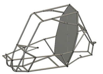
Chassis Requirements
Goals
|
Skills
CAD | Fusion 360 Manufacturing | TIG Welding, tube notching and bending Design | Design for Manufacturability Leadership | Project Management, collaboration between subsystems |
Material Selection | 4130 Steel Tubing
Requirement | Circular steel tubing with carbon content at least .18%
|
Material Advantages
|
Material Properties
|
Torsional Rigidity | Testing and Validation
|
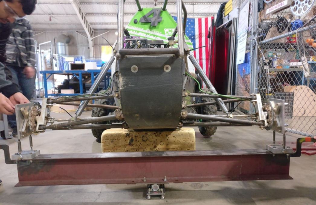
The torsional rigidity testing jig, shown above, was designed and built by a FSAE senior project group. It was adapted to fit the Baja SAE car was used to determine the torsional stiffness of our 2018 chassis. The shocks were replaced with rigid rods to isolate the torsional deflection to the chassis.
|
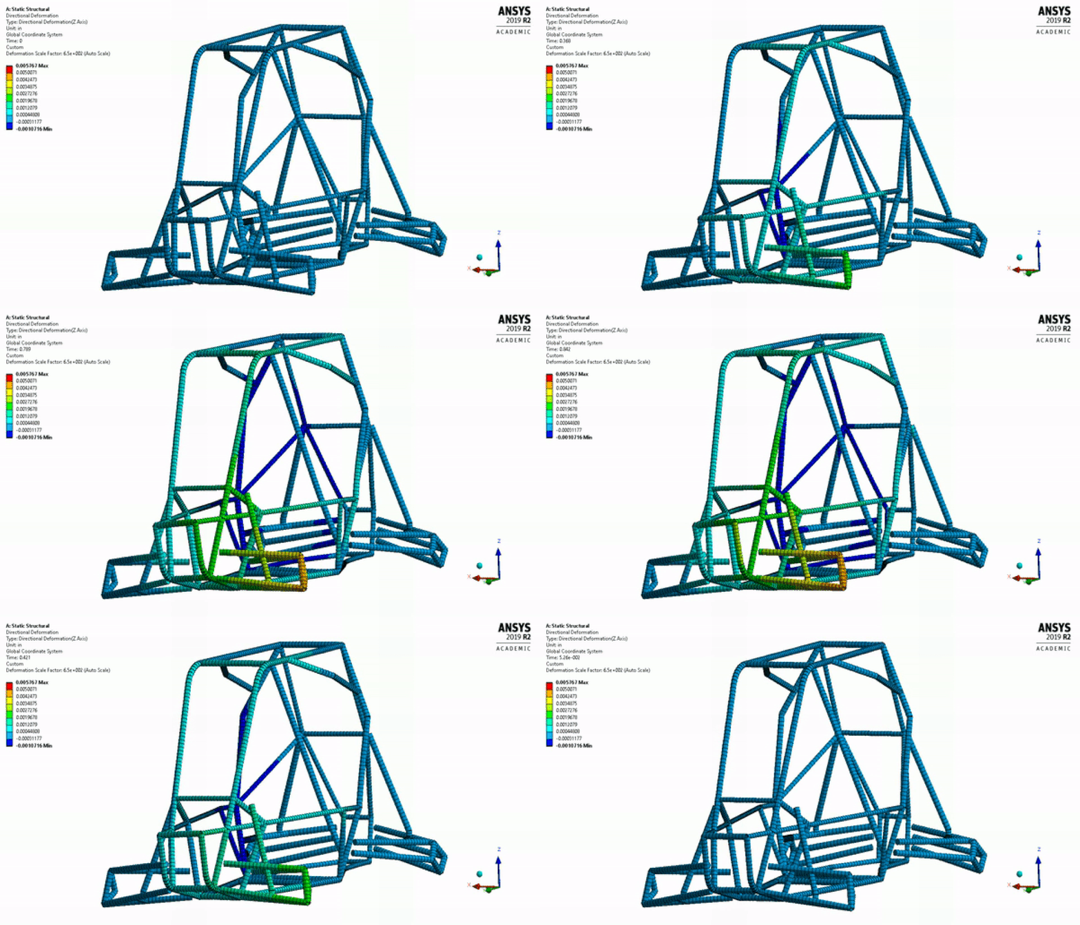
In Ansys, we created a model of the 2018 chassis and replicated the conditions of the torsional rigidity test. A load was applied to the front hub and the rotation of the opposite hub was measured.
|
There was a 1.3% error between the experimental data and the FEA model. Sources of error during this experiment could have resulted from manufacturing tolerances, added components in the car, and limitations in the test equipment. The purpose of this test was to create a torsional rigidity Ansys model that is validated and can be used for future Baja cars.
The torsional rigidity tests were performed by the FSAE senior project team and the Ansys modeling was performed by KC Egger.
The torsional rigidity tests were performed by the FSAE senior project team and the Ansys modeling was performed by KC Egger.
Rear Bracing Analysis
|
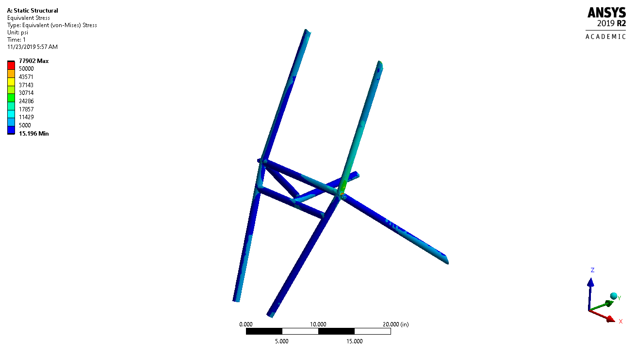
A simple FEA study was performed to determine if the tube wall thickness in the rear bracing of the chassis could be downsized from 0.049" to 0.035". For this model, the ends of the tubes were fixed and a load of 1500 lb was applied at the right rear shock mounting location. This was to simulate a worst-case full suspension bump load and check for material yielding.
The welds were modeled as fillets, and it is expected that there would be a false stress concentration in the FEA model at the welds. Realistically, the material properties change locally and that area would require further analysis. The maximum Von-Mises stress seen (except for the local area around the weld) was approximately 30,000 psi which gave us a safety factor of about 2.1. We manufactured the chassis with the wall thickness of 0.035" and planned to validate the model with a static weighted deflection test. Unfortunately, the lockdown from Covid-19 brought our season to an early end. |
Manufacturing
|
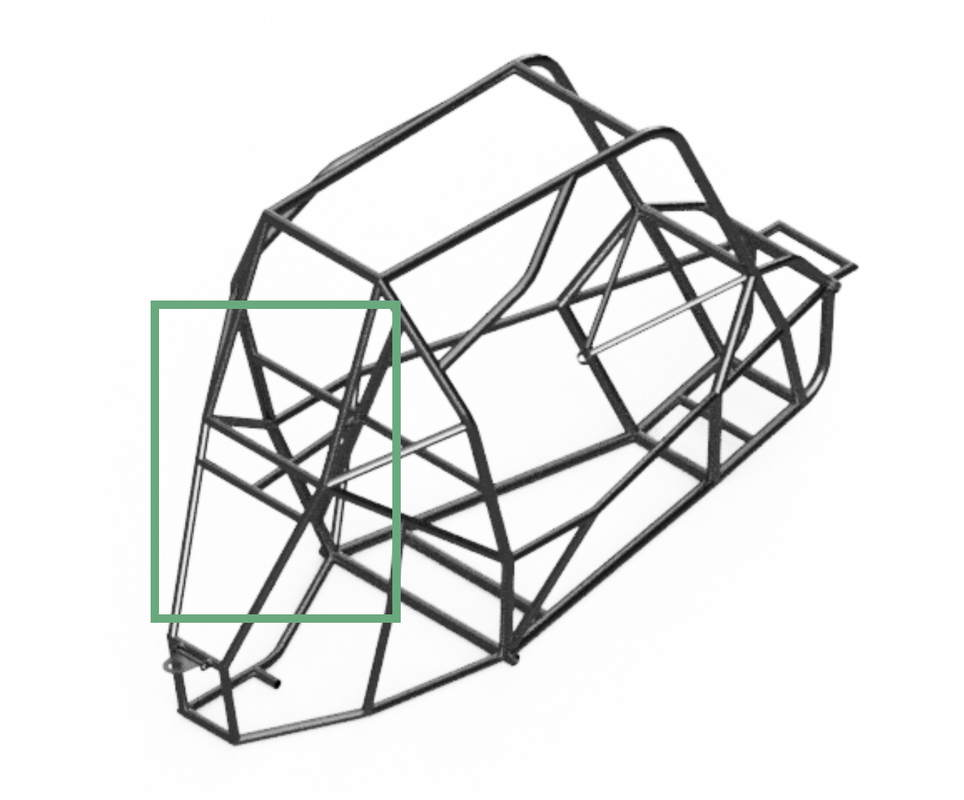
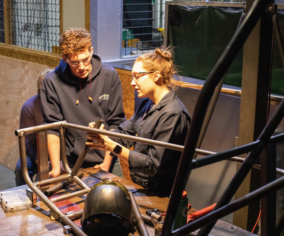
The chassis was built with TIG welding and a rotary sander for notching tubes. First, the floor and firewall were separately laid out, jigged, and welded on flat tables. The layout for each of these pieces was created by scribing lines onto a table with the proper tube centerlines lines that were then offset to account for the tube width. Square jig blocks were welded to the table at the outer edges of the tubes to provide a slot for them to sit while being welded. We then proceeded to cut, notch, miter, and weld each tube together as the chassis was built from the table upward.
The construction of the chassis taught me about anticipating manufacturing bottlenecks and utilizing my team resources. The biggest challenge I encountered was being able to measure the angle of the tubes properly to ensure that it was being welded in the correct position. Due to the nature of magnetic angle finders, several times the tubes had to be cut out and re-welded to be in the proper position. |
