September 2021 - June 2022
|
PROJECT PURPOSE | Create a platform for autonomous vehicle research by converting a go-kart’s steering and braking systems to be controlled electronically.
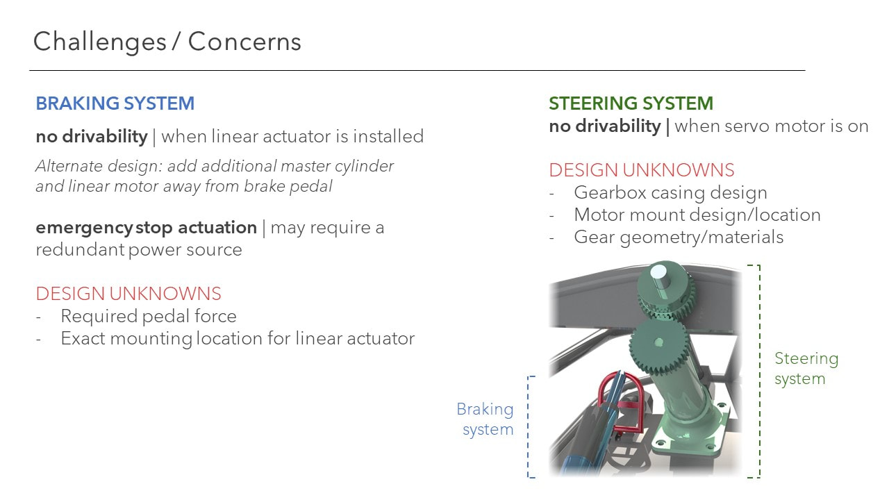
DELIVERABLES | Steering system, Braking system, Emergency Stop system |
|
Project Timeline
2021September
October
November
2022January
February
March
April
May
|
Vertical Divider
Initial Project Conception
Interim Design Review (IDR)
Critical Design Review (CDR)
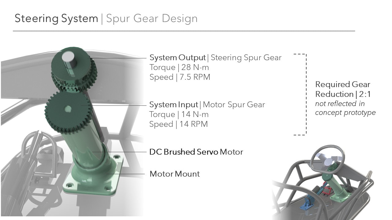
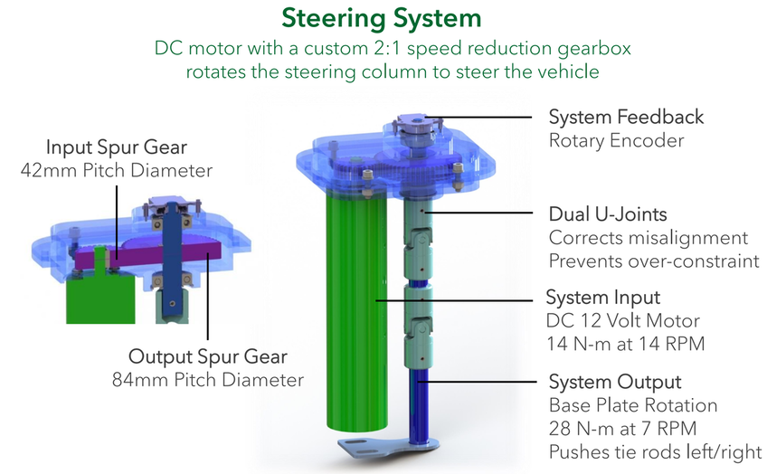
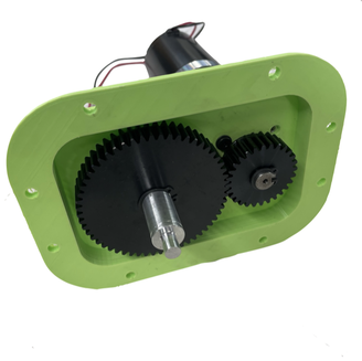
Our team presented the final design for each our systems in order to get approval to move forward with manufacturing. I focused on the design and analysis of the steering subsystem by designing a custom 2:1 gearbox to integrate the provided motor into our go-kart steering design. Manufacturing
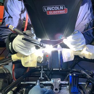
We worked in the Cal Poly Machine shops to manufacture our prototype based off the designs. I led the team through the manufacturing while working on the manual mill, manual lathe, TIG welder, and CNC mill.
|
Manufacturing
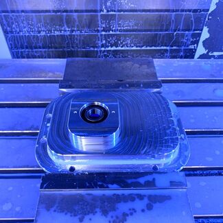
CNC Mill
I machined the gearbox case using the Haas VF3 and the Haas Minimill. The machining process was done in three operations: the first machined the outside of the case and roughed the inside of the bearing bores, the second operation machined the inside of the gearbox case, and the final operation finished the bearing bore and the locating features. This was done to eliminate custom tooling and produce the required tolerances for the bearing fits. I expected the extruded stock to warp as material was removed so I finished the inside of the bearing bores in the final operation. |
TIG Welder
All of the gearbox mounting tabs and tube are 5000 series aluminum so that they could be easily welded to the provided chromoly tube frame. We used a TIG welder in the Cal Poly Machine shops to weld the tabs and mounts to the frame of the cart. The aluminum gearbox case was used to ensure proper mount spacing to eliminate required welding fixtures and reduce manufacturing time. |
Assembly Fit Check
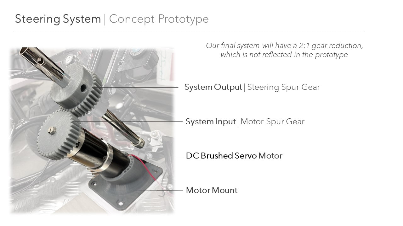
Prior to each major stage along the design and manufacturing process, I conducted a 3D printed assembly fit check. This helped reduce the time required for the design process by allowing me to physically inspect the design and review any details that were overlooked before beginning final manufacturing. For example during the first fit check, I discovered that the motor key was incorrectly sized because the edge of the keyway was rounded. This reduced the available keyway length I could use because we had purchased square keys. With a larger budget and timeline, I would have re-ordered rounded keys; however, I was able to grind down the purchased keys to produce a sufficient prototype. |
Preliminary Design